When starting the design process for any manufacturing technique, it’s helpful to model the part in the same way that the machine will build it. For extrusion, begin with a sketch of the profile and then extrude out from there. For sheet metal, start with the sheet and add the bends and holes. To design for 3D printing, begin with the base that will sit on the printer’s bed and then build up from there, similar to how the printer works. In the world of 3D modeling, it’s easy to create designs that are impossible to manufacture in real life. This technique helps designers stay grounded in reality and avoid getting lost in the program’s functionality. We’re here to assist experienced 3D modelers in creating new parts using 3D printing technology. In this section, we’ll discuss the orientation of the 3D printed part, focusing on the flat spot and support traps.
The Base
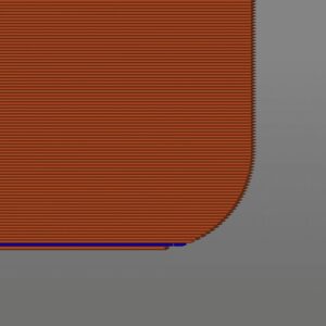
When it comes to 3D printing, it’s important to plan out what will be touching the build plate from the beginning. The printer usually starts with a flat spot, which is often the base of the object being printed. To avoid any unwanted features sticking out, it’s recommended to keep the first layer large and flat instead of incorporating a small feature with lots of support. This can help prevent mistakes like the one shown in the following example. It involves laying down layers of plastic on top of each other to create a final product.
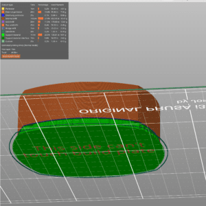
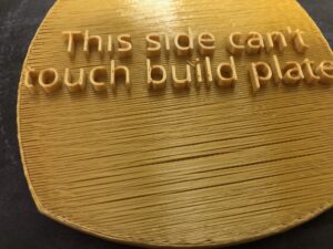
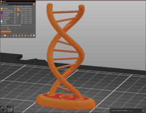
I’m sorry to say that this object cannot be printed without support as it has a protruding text feature that creates an elevated flat spot. However, supporting the entire object above the build plate would result in a stringy appearance, which most customers would find unsatisfactory. Instead, you can view the object by clicking on the provided link, rotating it to view the round edges, and finding a flat spot to print on.
Design for 3D Printing: Electronics Enclosure
When examining something that is frequently printed, such as an electronics enclosure, it’s important to keep in mind that the design should be relatively simple. An open box with five sides, buttons, lettering, and holes for plugs is typically the best way to go. However, there are numerous ways to make it unprintable. For instance, if you round the top, create protruding extrusions like the above model, or include mounting holes on the inside that require support, it may become problematic.
I’ve noticed that mounting holes on the inside of a box can lead to support traps. It’s frustrating because support needs to be built to create the part, but it’s impossible to remove the support once the model is manufactured. Unfortunately, changing the orientation of the model won’t prevent support traps. However, adjusting the design of the 3D model itself is the solution to avoid support traps.
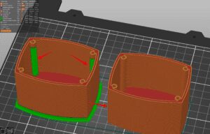
Extending the mounting holes to the bottom of the enclosure is a common method for eliminating support traps. This allows the printer to create a natural build up from the bottom to the top of the mounting hole. If extending the holes is not possible, another option is to construct the mounting holes at a 45-degree angle. This angle allows the material to build up without requiring any support.
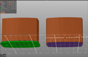
In order to achieve a smooth appearance when printing, it’s important to keep the bottom of the printer flat (the side that touches the build plate). This flat surface will serve as the base for the printer to build up the other walls. If the bottom of the model is rounded, support may form there, as seen in the picture on the left. As it turns out, flattening out the bottom will ensure a good first layer of plastic for the printer to build upon.
You never know which small features can greatly impact your product’s appearance and durability. Check out our other articles for more information on 3D modeling for 3D printing.