Fillets are a great option for removing sharp edges and stress relief to hard corners. However, it’s important to keep in mind that all fillets are not the same while 3D printing. The orientation matters with every design since the amount of detail is constrained to its orientation. This is why, if fillets touch the bed in the z-direction, you can run into problems of sagging or unsatisfactory surface quality. In this guide, we’ll talk about avoiding these mistakes when diving into fillet design.
What is a Fillet?
Fillets were first introduced in the machining world of metal parts. This is a technique that rounds a corner to a certain radius. This can be done for inside corners or outside corners.
Fillets in Machining
Mainly, these were created to relieve stress on internal edges. In mechanical engineering, the hard 90-degree angle creates a force concentration that will break the part under a load. The fillet edge will spread out that force and create a stronger part.
As an added bonus, fillets totally eliminate sharp corners. When parts are handled quite often, external fillets are added to the design so users don’t need to use any gloves.
Fillets in 3D Printing
As we turn to the 3D printing world, fillets don’t have all the benefits they have in machining. Parts that come off a 3D printer, whether there are fillets or not, can be handled without gloves.
That just leaves the benefit of reducing stress concentrations on interior corners. This is great for plastic parts since it’s generally accepted that they are weaker than metal. You’re less likely to bring it above the breaking point, depending on the force.
When 3D printing, you see a range of designs come through the ordering process. Some have all their edges filleted, and some have none. It’s just up to the designer on what he wants to do. I think the filleted edges on plastic parts became popular in the injection molding process. Personally, I think the rounded edges make the parts look much more professional.
What is a Chamfer?
Chamfered corners can be used on an interior or exterior corner, just like fillets. These are a sloped edge normally with a 45-degree break, just like the image below.
Chamfers are not normally designed on an exterior corner. In the machining world, you could still have some hard edges to cut your fingers on. It wouldn’t allow the part to be handled without gloves.
However, on the inside corner, chamfered edges are used quite a lot. Chamfered edges have a lower stress concentration factor than even fillet edges. If your part is not providing enough strength with just a fillet, you could use a chamfer instead to increase these dividends even further.
Fillet vs Chamfer
Both the fillet and chamfer are features to eliminate sharp edges on the interior or exterior corners. The fillet uses a radius, while the chamfer uses an angle to reduce sharp edges.
For outside edges, the fillet is normally the best bet. Normally, this makes the corners less likely to break, and it doesn’t snag some skin during use. For 3D prints, designers will add fillets all around the part for aesthetic purposes, but it’s not really necessary.
For internal features, either edge can be useful depending on the force that the part will undergo. For less stressful situations, the fillet is very useful, and for more intensive situations, the chamfered edge should be used.
Also, I would lean more towards designing fillets if a lot of hands touch the inside corner. The smooth edges will feel much better than a chamfered edge.
With these comparisons, you should be able to pick the correct feature when comparing a fillet vs chamfer.
How to Design Fillets for 3D Printing
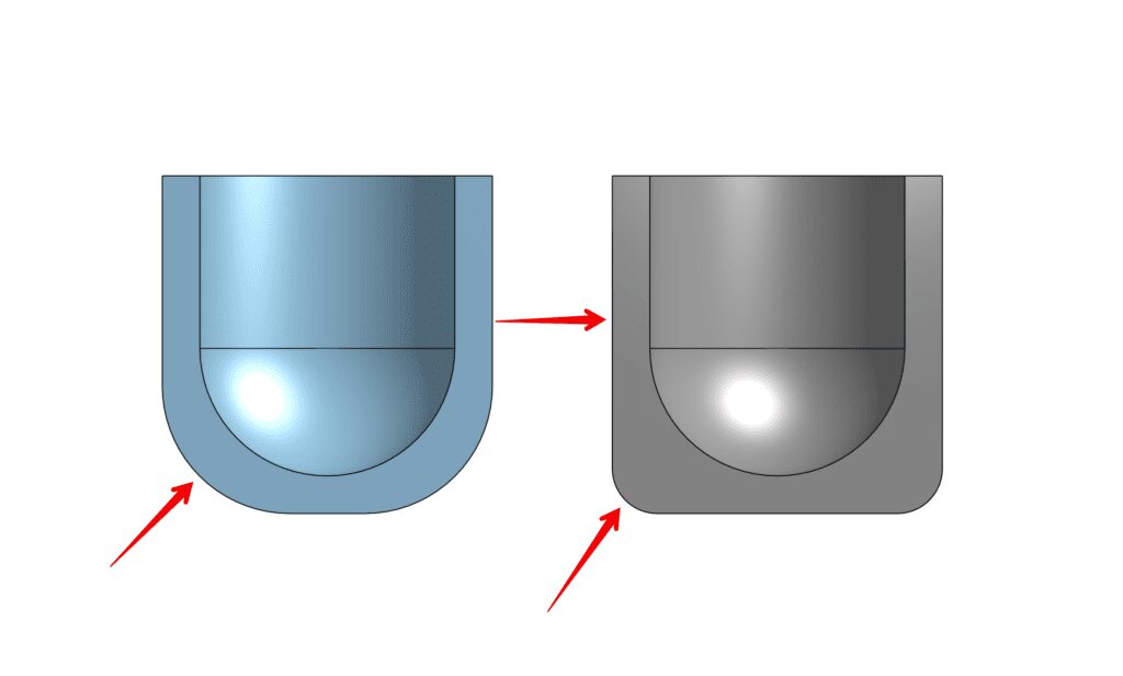
When talking about fillets for 3D printing, pretty much anything goes except when you want to create an external fillet in the z direction that sits on the build plate. If you don’t, it can lead to quality defects and sagging.
Two different variables are in play here. Since we are in the z-direction, detail is directly related to the layer height used by the printer. Also, the fillet radius plays an important role. We’ll go over their relationship a bit further down the guide.
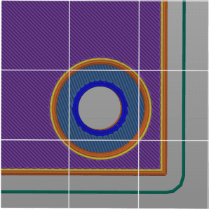
Before actually printing the object, you can tell if the fillet will come out with a smooth surface or not. In the slicer(we use PrusaSlicer), after you slice the object, look at how many overhang lines show up on the fillet. If you have more than one show up, the fillet will need support, or it’ll come out with poor surface quality. If you have one line or less, you will more or less get a perfect fillet radius.
If a service like our own is producing the part, you can still run the test from home. Just use .2 mm layer height and slice the part with Prusa Slicer. This will ensure you have no surprises when you receive your order and the quality is not up to your standards.
As we talked about above, there are two factors at play with fillet design: the layer height and fillet radius. Essentially, the bigger the radius, the smaller the layer height will need to be. If you want a quick reference on the relationship between these variables, there is a table below:
With each layer height, there is an associated maximum fillet radius. If you go over the maximum fillet radius in the table, then the printer will have trouble creating your rounded corners.
Also, it’s worth noting that fillets in the xy plane will print just fine without any issues. However, other fillets in the z-direction, if created too big, will have a “stair step effect to them, which means that you will be able to literally see the layer lines on the top of your part. If this is a concern, you can learn more about this feature in our guide, “Design Layer Lines for 3D Printing“.
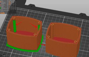
Example: Design Fillet in an AirPod Case
In This example, we will be using our newfound knowledge to make an AirPods case. The case will maintain an even thickness around the AirPods so it can protect it from bumps and bruises. However, if we print the case on the build plate, it’ll create a large exterior fillet that will have unsatisfactory surface quality. Using what we just learned, we can take this rounded corner and decrease its radius. According to the table above, we’ll use the fillet command to bring down the fillet radius to 0.15 inches. This is a bit counterintuitive since the inside radius that holds the AirPods will stay the same. With this new design, manufacturing costs will come down since there is no need to support the outside walls. Also, the manufacturing process will become more efficient since the part will be ready to use right off the build plate.
Hopefully, by now, you are an expert in the manufacturing of fillet and chamfer. Please feel free to reach out with any questions. Take this new fillet engineering to the test by placing an order through us. We will be happy to help with any manufacturing need.