When using 3D printing, each layer is built upon the previous one. Designing for 3D printing requires consideration of this sequential process to optimize part manufacturing.
Unlike other manufacturing techniques, this method offers greater design freedom but has some limitations.
In this guide, we will review the few limitations when designing parts for the printing process.
How to Design for 3D Printing
When thinking about the design process, I like to think about how this part will be made in real life and go through that same process in my CAD software. With 3D printing, the printer will start with the base and go up the part creating the features you need. For this guide, we’ll take the same approach: starting with the base and then moving up the part into features you’ll run into.
For the best CAD software to create your models, the one that we use is Fusion 360. This has a number of features that are great to design for 3D printing. For an in-depth look into design software, check out the guide below.
Orientation
In my experience with 3D printing, orientation is a key factor to consider when slicing your model. If you want the printer to build up effectively, it’s best to position the largest flat surface on the build plate. I like to think of it as building up like a pyramid or cone. You’ll start with the large flat surface and then build up to the smaller features.
Orientation is the most critical design element in this guide. The other features in this guide will help determine a different orientation or create support structures to guide the printing process.
Base
Nine times out of ten, the largest flat surface will be used as the first layer of your print.
Therefore, this feature should not be rounded or given small extrusions that elevate it above the build plate.
In order to make sure the base lays flat on the build platform, any features on the bottom should be an extrude cut. Details as small as 1/32nd of an inch will show up on any part of your printed part.
Layer Lines
3D printed objects often have layer lines, which are visible and can give the appearance of stair steps on the final part and greatly affects print quality.
Layer lines are a function of layer height and the angle of the part. The smaller the resolution, the smaller the angle you can create.
Designers can prevent layer lines by orienting the part along the xy plane. Alternatively, they can eliminate the angle completely by making the part square.
Fillets
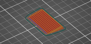
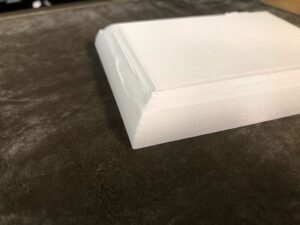
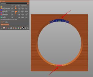
Fillets give your models a clean look, but, if they have a large radius, it is best not to place them on your build plate.
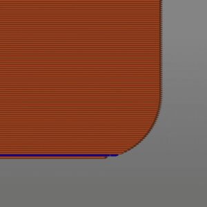
Large radiuses create an overhang that has to be propped up with support. This can lead to unsightly scars, and, if you don’t support it, the model will have obvious drooping.
To avoid this issue, just create a smaller fillet in the design software. A good rule of thumb is after the model is sliced, you shouldn’t see more than two overhang lines. If you do have more, this means the file will fillet will droop during the manufacturing process.
Overhangs
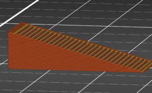
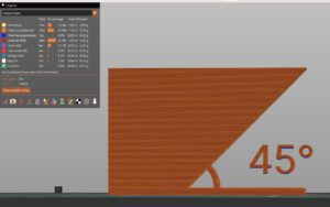
Overhangs occur when a wall angles out from the base of the object. Shapes like an upside-down pyramid or an upside-down trapezoid can fit this feature. You’ll want to design parts so the 3D printer can overcome this design feature.
The 3D Printer can only support an angle from the build plate to the wall of 45 degrees or more. Essentially, this means there will be no artifacts on the part as long as at least half of the top layer is on top of the subsequent layer. If the designer goes below that angle, support will have to be added to hold up the part.
Most slicer software will identify these pesky features. After slicing an stl file, look for any overhang features that aren’t supported. If you do find any, it is best to avoid overhangs by going back into the CAD software and editing the feature. Alternatively, you could just add more support to the object in the slicing software.
Bridges
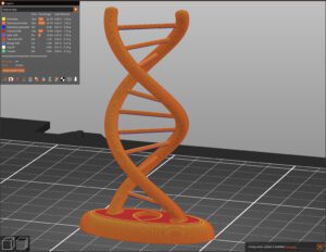
A bridge is exactly how it sounds. It is a vertical length of material that stretches between two legs of a part. It is kind of like the space between the two legs of an “H”.
Through the rules of 3D printing, small bridges don’t necessarily need support and can be printed out of thin air. This depends on the material and length of the bridge. It is recommended to avoid large flat surfaces while using bridges.
As a general rule of thumb, PETG can only handle small bridges, while PLA can handle longer ones.
Unsupported Edges
Unsupported edges are flanges that stick out vertically from an object, looking like a bridge with no support on one side. To make these objects effectively, the slicing software will have to include support material so one side of the bridge doesn’t sag.
It is recommended to avoid using unsupported edges during the design phase. No one wants to post process their parts. If there is a need to print such edges without support, you can save time by rotating the object 90 degrees to ensure that the feature prints upwards. Another option would be to add a chamfer to transform the feature into an overhang.
Islands
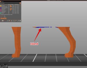
Islands are features that start in mid air and then have to be connected to the rest of the body of the model higher up in the part.
These are normally prevalent in the CAD model, like a dog standing up on all four paws. To build this with a 3D printer, you would have to start with each leg of the dog separately and then merge each leg with the body that is built in midair. In this case, in particular, the Island would be the belly of the dog. This 3D Model is very hard to create since you have to get 5 different pieces to meet up. one slight movement of any of the parts will cause an unsightly layer shift, and the dog will have to be reprinted.
Support Traps
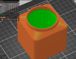
Be wary of support traps in your design. These are features that require support material but cannot be removed after manufacturing.
Take a jar-shaped container, for instance. In this case, before the opening of the jar starts, it’ll close in a little to go from a square shape to a circle. Where the jar closes in, you’ll have to add supports with your slicing software, but there will be no way to get them out with a knife or pliers. The only way to print this kind of object out is not to add any supports at all and hope that the opening isn’t collapsed.
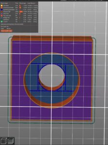
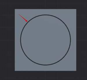
Vertical Holes
As a general rule of thumb with 3D printing, holes that are printed in the vertical dimension can be printed without support but the dimensions will be slightly off on the top and bottom.
It’s important to remember that your object is going to be sliced into layers in the slicing software. It’s kind of like the resolution on a TV or video game. Typically, each layer height will be around .2 mm thick, so the top and bottom will be cut off.
If this “feature” is causing an issue, you can either add a teardrop shape at the top or cut a trapezoid to stabilize the bridge. Both options will achieve the desired outcome.
Floating Holes
Floating holes are holes parallel to the build plate up in the z direction. Normally, you’ll see these features in countersink holes, so you can use screws but the head won’t stick out.
This is a very common feature in 3D printing and most of the time, the part works out where you need to support these features in the slicer software.
There is a clever technique that allows you to print these holes without support at all. Go to the guide below to add this design skill to your arsenal.
Threads
Threads are a unique feature of the 3D printing process. In all other manufacturing processes, threads must be added in post-production. 3D Printing is the only process where threads can be added into the modeling software and then can be produced right on the print bed.
This is why CAD software like Fusion 360 is so powerful. You can add 3D printable threads right onto the part with one click. All tolerances will be added automatically, so your parts will just fit together in the end.
For adding machine screws to your printed part, I recommend adding heat set inserts instead. The plastic threads will just get eaten up by the metal screws. These heat inserts are really simple to install with just a soldering iron.
Text and Logos
At our plant, we get a range of extruded text from our customers. Some people extrude it out and others use the extrude tool to cut it in, but what really is the best way to print parts with text?
We have found that the most effective way to add text to an object is by using an extrude to cut the text 1/32nd of an inch deep.
The printer can create text without support in the vertical direction and won’t get in the way if it is located on the base of the model.
Tolerances
When creating assemblies, you’ll have to build in a small gap so the parts print properly. If you make a hole and a peg the same size, they won’t fit together as per the laws of physics.
In the CAD software, leave a gap of about 1/32 of an inch for a tight fit. For looser fits, use 1/16th of an inch.
Orientation for Strength
The most common spot for a part to break is along the layer lines. For every layer of plastic that is laid down, it creates a weak spot for the part to break.
Ideally, you’ll want to keep your printing horizontally so that the least amount of layers are created. As a side note, this also reduces the print time to manufacture.
If this isn’t possible, I would lay down layers perpendicular to the largest amount of force the part will take. This will give it the most strength possible.
For example, when creating a shaft, the natural way to print it is vertically, but this creates weak spots every time a layer is created. In 3D printing, it’s best practice to print this horizontally so that the layer goes all the way through its cross-section.
Materials
We can go down quite a rabbit hole with materials, so we’ll keep this one brief. We’ll talk about 3 materials. PLA is the material most people start out with. It is made for the use of rapid prototyping or highly detailed models. The reason is it doesn’t have much heat resistance or strength.
ABS will be the material you go to if you need heat resistance and strength. The only problem with this material is, that as it cools, it shrinks (sometimes up to 20%). This can cause warping or splitting issues with certain features.
If you have warping or splitting issues, and you need strength and heat resistance. Your best bet is to go with PETG. This material doesn’t warp as much as ABS, but it also doesn’t have as much heat resistance or strength as ABS either. PETG is the material right in between both PLA and ABS. If you need more strength than PLA, but your part is prone to warping or splitting, then PETG will work for your part.
This is a simple method to figure out what material to use for your part. As we add more materials, this can get more and more complex. We’ll do a more in-depth guide soon on material choice.
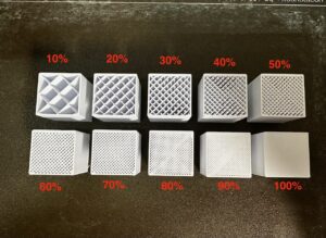
Infill
Infill is a setting in the slicing software that determines how hollow your part will turn out. 0% being totally hollow and 100% being totally solid.
This is a very useful setting when looking at manufacturing for strength versus cost. The lower the infill, the weaker the part, but you also save time and material. Saving material and time will also save in cost, so there is quite a lot of benefit to looking at how much infill you use.
It takes a bit of a learning curve, but if you would like to check out this setting in a free slicer, the best one to use is Prusa Slicer (the best slicing software). Other programs to look at include Cura or Mesh Mixer.
Multi Color Design
New advances in 3D printing now enable manufacturers to create objects using multiple colors of filament. This can be done with the slicer or 3D modeling software.
Within the CAD software, separate each model into separate objects based on the color change. Export all objects as one .3mf file to input into the slicer. This can also be done by exporting each object as its own .stl file and dragging all files at once into the slicer software. Once in the slicing software, you can assign a certain color to each object.

Alternatively, when utilizing the slicer, you can color color the object with the painting pallet. You can color entire sections with one click or use the brush mode and just color the sections you want. For more details about these features, check out the blog below!