Counterbore holes are a common feature throughout most 3D-printed parts. It’s easy to design an extrude cut for the bolt head, but what most people don’t realize is that the counterbore holes will have to be supported during the manufacturing process. The perimeters of a layer are always reacted first, so for every counterbore hole, the outline of the hole will be created first in midair. Without support, this creates a collapse in the hole and reduces the strength of your part. In this guide, we’ll walk you through some easy steps to eliminate this pesky problem. We’ll take you through step by step on how to design counterbore holes. You’ll be able to use your parts right off the build plate.
What are Counterbore Holes?
Counterbore holes are a manufactured hole made for fasteners such as a hex head, socket head cap screw, or lag bolts. Mainly, it’s created so the head of the screw sits flush with the surface of the part. Contrary to a countersink hole, a counterbore hole has a perpendicular surface for the head of the bolt to seat inside the flat bottom. This feature actually allows it to hold more force than the alternative holes—one of the reasons it’s widely used in the 3D printing design process.
How to make a counterbore hole
Machining a counterbore hole is a pretty simple process, whether you are producing wood or metal parts. Generally, there are two ways to make counterbore holes: one with some counterbore tools and the other using multiple drill bits.
Counterbore tools are drill bits that are specifically made for the counterbore process. This will be a bit with two diameters: the tip will have a small diameter, and then as you go up the cutter, you’ll have a larger diameter for the screw head. Basically, if you get the specialty bits, it’ll cost you less time, and you’ll end up with holes that are in the center of each other.
If you don’t want to buy the specialty bits (I know I don’t), then you can use two different-sized bits to get your counterbore hole. If you have one, I recommend using a drill press to keep everything centered and lined up but a simple drill will suffice as well.
For the pilot hole, you’ll want to measure the diameter of the threads and drill a hole about 1/32nd of an inch larger than the threads. The clearance will allow the threads of the bolt to go in without catching on the side of the hole.
Next we’ll drill the counterbore hole. This is the step that makes the bolt flush with the surface. Take measurements of the ffastener head. We’ll use the same clearance of 1/32nd of an inch for the fastener head and the depth will be the length of the head so the top of the head will sit flush with the surface.
And there you have it! Just a few easy steps to make a counterbore hole.
Design a No Support Counterbore Hole
Counterbore holes are a common feature in the 3D printing world because they can be programmed right in the part. With other materials, this is an entirely extra step in the manufacturing process. No post-processing is needed if you add just a few extra steps to your workflow.
We will first start out with a counterbore hole modeled in your favorite 3D modeling program. This can be done with the same steps outlined in the last section. Instead of drill bits, you’ll just use extrude cuts on the computer. If you’re new to 3D modeling software, we have a comprehensive guide here. In this example, we’ll be using onshape to create our model. Your screen should look like the one below.
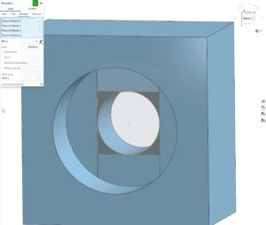
To start, we’ll want to create a sketch on the flat bottom of the counterbored hole. We’ll draw two parallel lines in the vertical direction. The endpoints will sit on the larger hole and the lines will be tangent to the smaller hole. It’ll give you a sketch that looks like the picture below.
Next, use an extrude to cut at a depth equal to the layer height your 3D printer will be using. It is imperative that you match this feature with the manufacturing process you are using. There is a chance this will not work if you don’t. Most of the time, this is 0.2 mm, so we’ll use this depth from now on in this example.
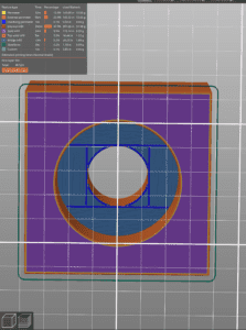
For the second and final sketch, we’ll set the plane to the surface of the last extrude. This process will be about the same as the last step, except the parallel lines will run 90 degrees from the lines we made in the last sketch. Also, these lines will intersect at the edge of the extrude, NOT the edge of the larger hole. Remember that each parallel line must be tangent to the inner hole. The final sketch will look something like the picture below.
Now, just extrude the last sketch. Make sure to use the correct depth according to the layer height setting you will use. Again, in this example, we will cut the second sketch 0.2 mm deep.
And there you have it! A great workflow to add to your 3D modeling capabilities. Once the part comes off the printer’s build plate, you can screw in your fasteners for a secure assembly.
As a pro tip, we have also found that you really only need to run this workflow on one of your counterbored holes. Typically, we’ll add it to all your counterbored holes in one fell swoop with a pattern or mirror function.
How it works:
This counterbore feature works by converting the first two layers of the hole into bridges. These bridges can span across the larger hole without the use of support and then props up that initial perimeter of the hole on the third layer. Basically, the two bridge layers act as support for the smaller hole. Thus, support is no longer needed for this feature.
Nut Inserts
As a side note, this workflow also works well for nut inserts. Typically, with 3D printing, you wouldn’t be able to make this feature in the xy axis since it would have to be supported (and you are not getting the support out of that hole). With the new workflow, you can create a supportless chamber for your nut, and, as a bonus, it naturally creates a cavity that captures the nut. No more tipping the part, and everything falls out during assembly.
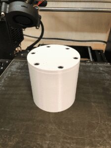
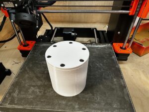
Cylindrical Sealing Container using Counterbore Holes
Let’s create a cylindrical container using the no-support counterbore hole. This container will include a lid and a base. The base will store your items for you. There are six bolts and nuts with a fastener size of M3 to seal this container, and this is our opportunity to use our new workflow.
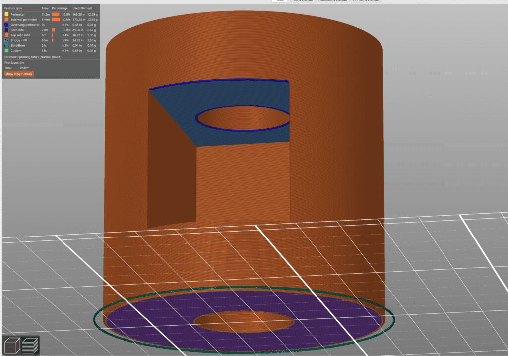
The base has cuts on the inside so we can slide in nuts. To manufacture these properly, we’ll have to add our feature to the insert cuts because we won’t be able to get any support out of these slots if we manufacture them the usual way.
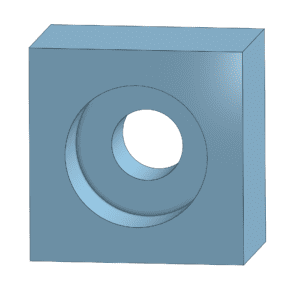
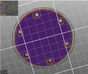
Let us focus our attention on the lid first since that will be the easiest to create. We want to be able to create counterbore holes in the top of the lid so that it will print with the top side on the build plate. The other side will have an extruded feature, so we can’t print it on that side. Here, we just create a counterbore hole like in the directions above. Make sure to measure the head of the metric fasteners so the hole size will be the correct diameter and flush with the surface.
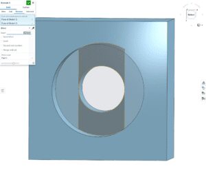
Once one of the workflow was added, I used a circular pattern to include the feature on the rest of the holes.
Turning to the base, this part was a bit tricky. Since the nuts were being inserted from the inside of the container, there was no way to pull support out of those cavities with some pliers or a knife. I added the same feature to these holes using the same workflow from above. The only extra step I needed to take is to create a section view so I had access to the inside of the container to create my sketches.
And there is a general idea of how to create this workflow for any of your projects. If you would like to download the files in this example, don’t be afraid to follow the link below.